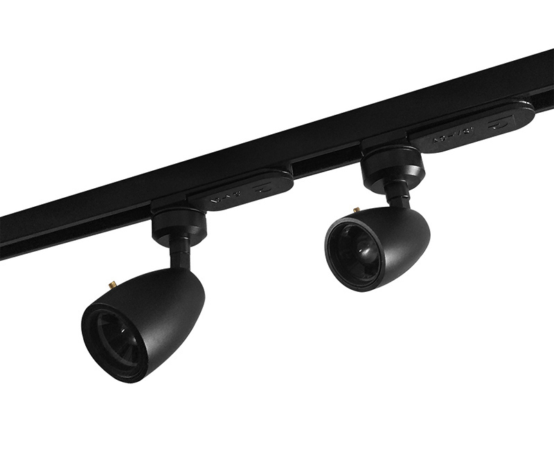
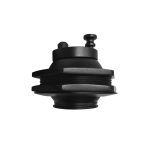
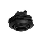
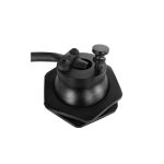
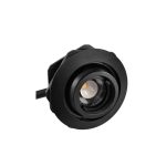
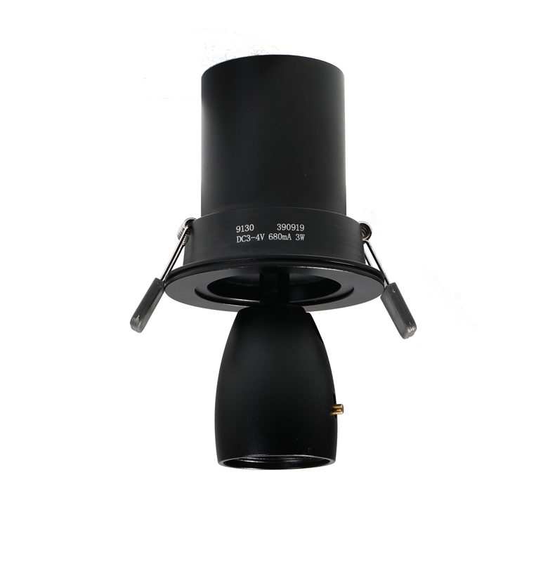
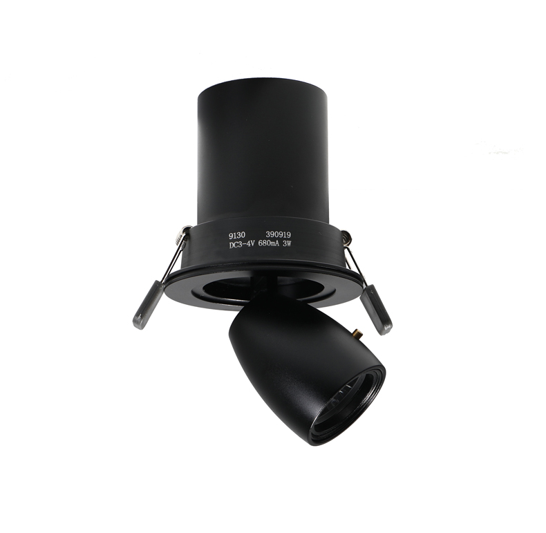
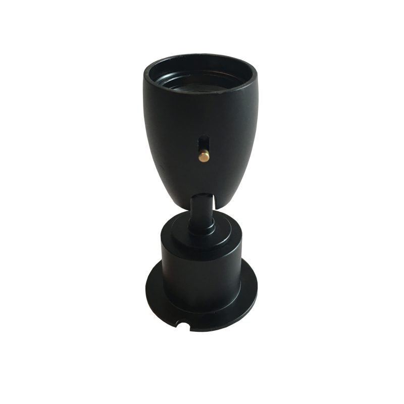
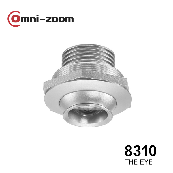
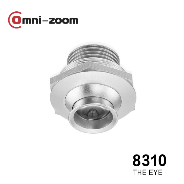
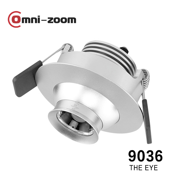
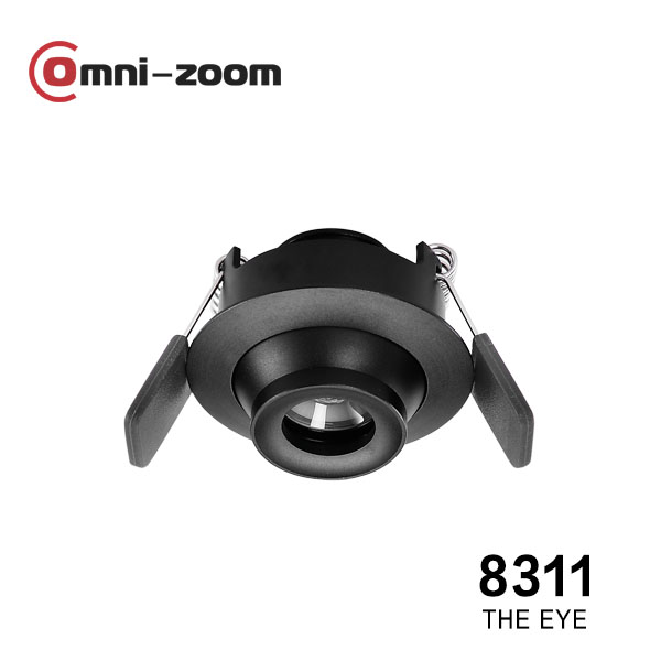
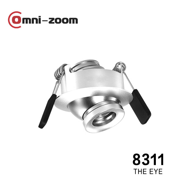
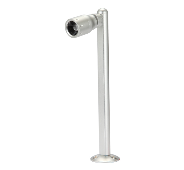
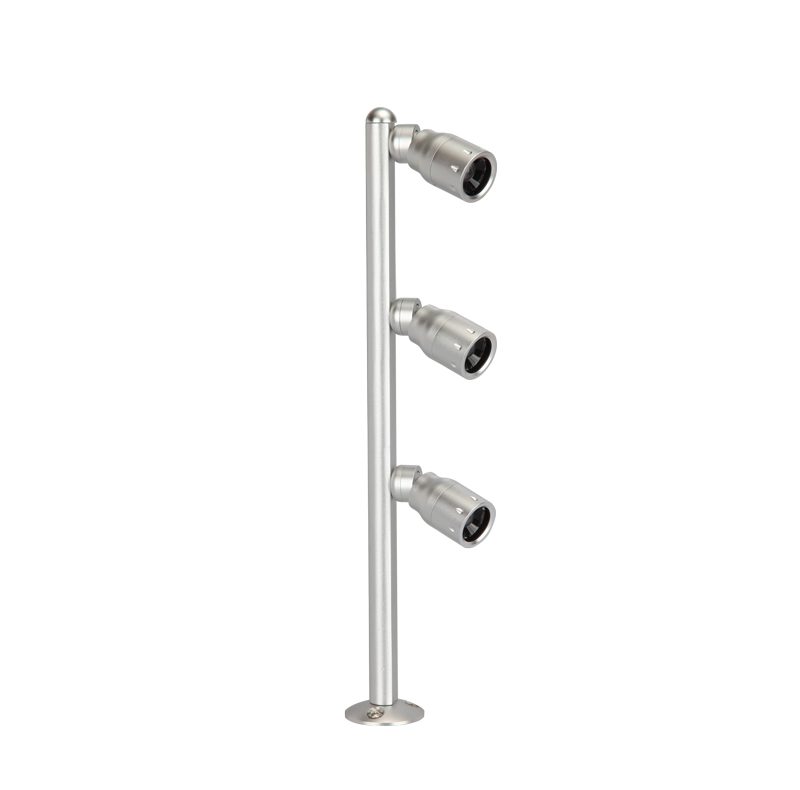
Rolux Um pequeno especialista para exibição / vitrine / mostruário #8288/8088 3W/1W
£1.00
"*" indica campos obrigatórios
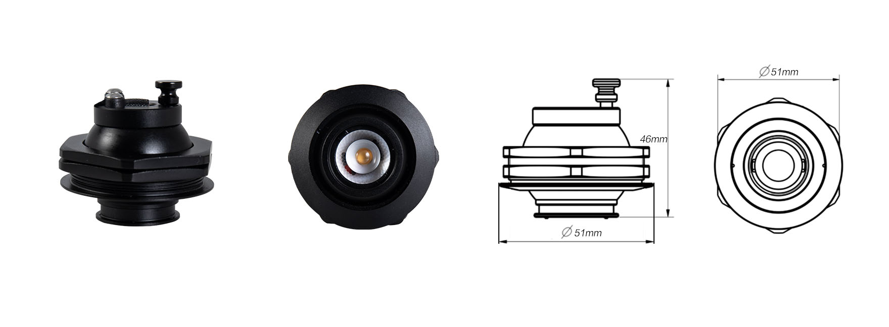
Rolux Zoomable(12°-50°)
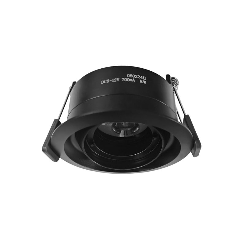
A small expert for exhibition showcase /cabinet display.
A considerate design more oriented from the spirit of sustainability and flexibility. A cabinet/showcase light can be controlled and maintained without opening the box!
Plus a light effect processing optical system to achieve an optimum illuminating effect.
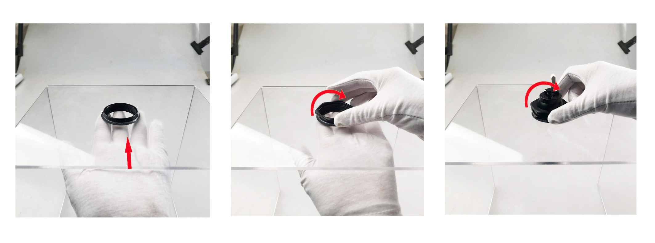
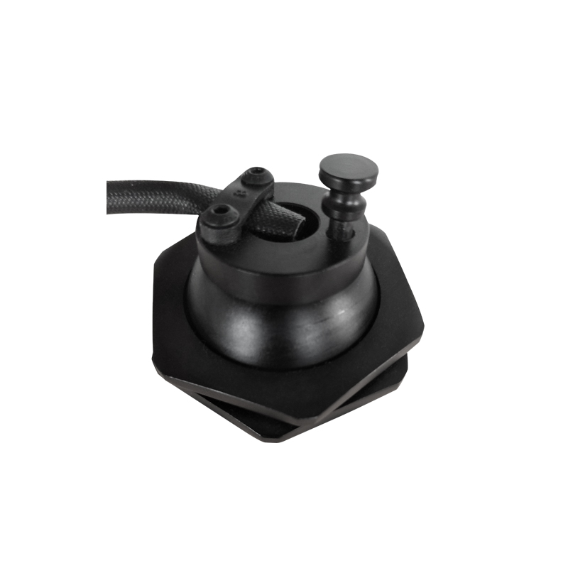
—Exteriors control and maintenance design
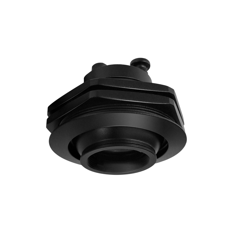
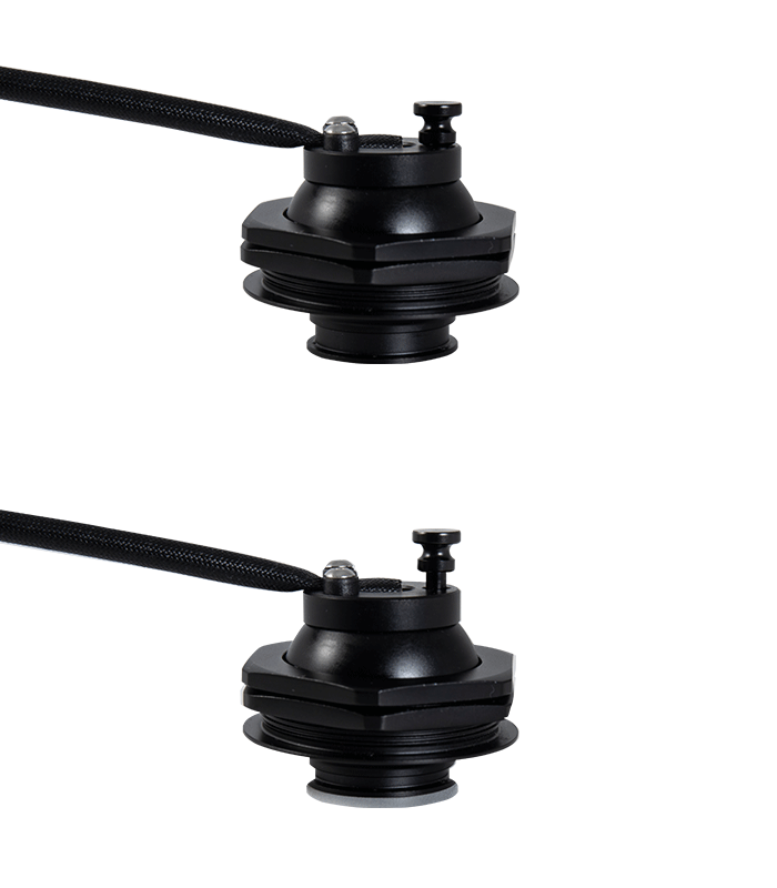
Control and maintain w/o opening the cabinet. That provides convenience for a more precise and perfect display. Equipped with set of pre-mounted brackets, the light can be changed and maintained easily. With an adjusting needle, the beam angle and the projecting direction can be adjusted freely.
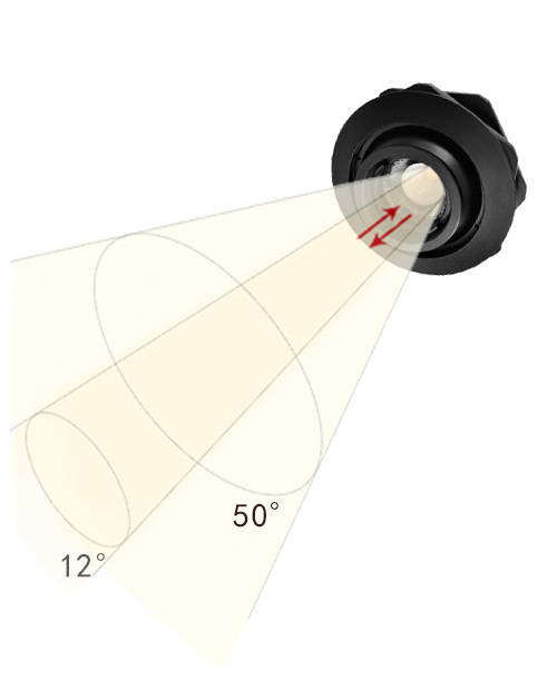
—Zoomable beam angle
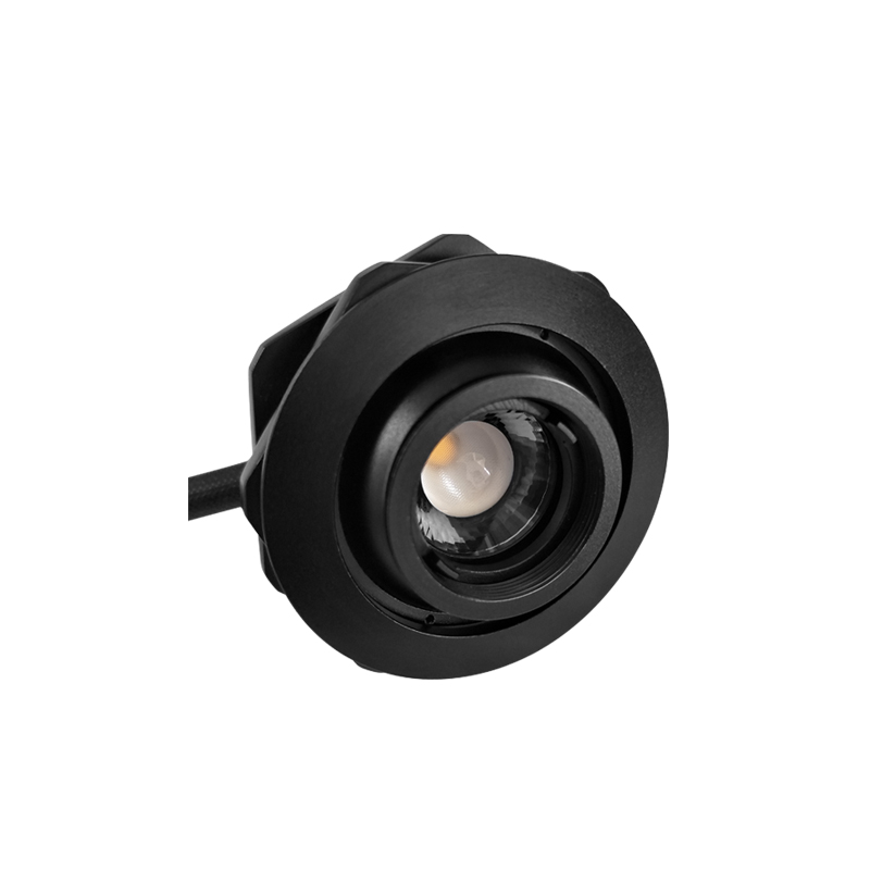
A Built-in patented lens can be adjusted to achieve a stepless light zooming from 12º to 50º , agile for displaying individual object,
by operating conveniently from outside of the enclosed showcase.
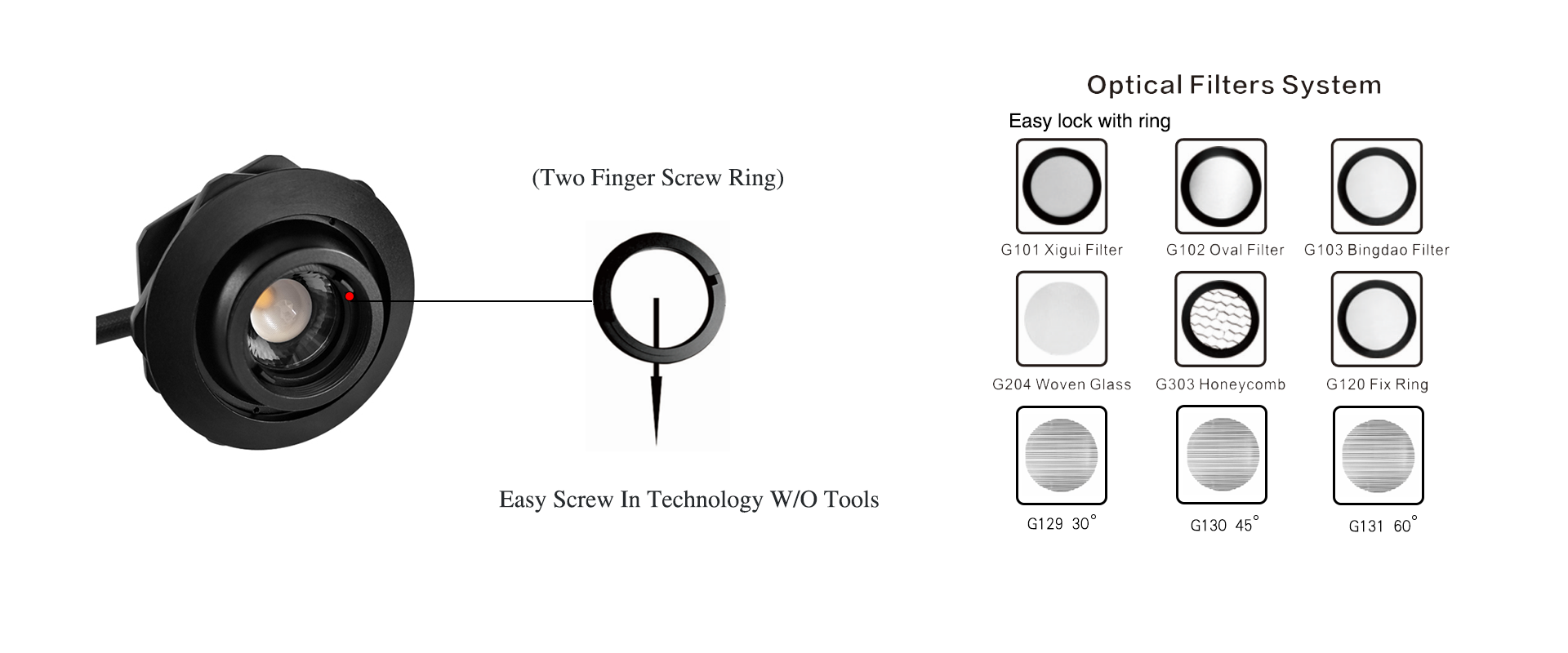
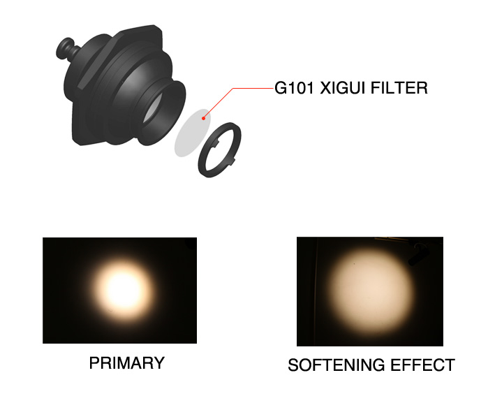
—Displaying expert with Tecnologia Y—a light effect processing optical filter system
How does Rolux work with Y-tech ?
For more characteristic displaying
You need a more penetrating or more softening light
The light texture can be changed with Y-Tech filters
For further effects
Y-Tech provides more options—the optical filter system
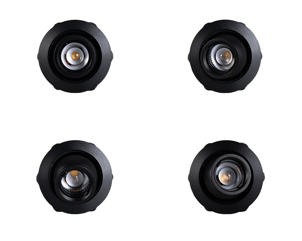
360°Horizontally directional
| Rolux #8288 1W/3W & Y-tech AC100-240V | ||
| Light remodeling round to oval | Wattage : 1W/3W | Quantity of LED: 1PC |
| zoomable technology | Beam Angle:1W/10°-38° 3W/12º-50º | CRI: >90 |
| Light Stretching | Lumen:1W 72 Lm/3W 165 Lm | Input Voltage:AC100-240V |
| Different light texture | Colour Temp: 2700k/3000K/4000K | Housing: Black |
| Different light colours | Installation: Recessed | Weight: 1W/200g 3W/200g |
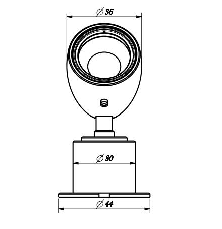
| Cutout: 45mm(42mm-51mm) | Certification:CE | |
| dimmable:Triac, DALI,… | Life time:30000H-50000H | Warranty:3 Years |
Rolux Zoomable(8°-38°)
A small expert for exhibition showcase /cabinet display.
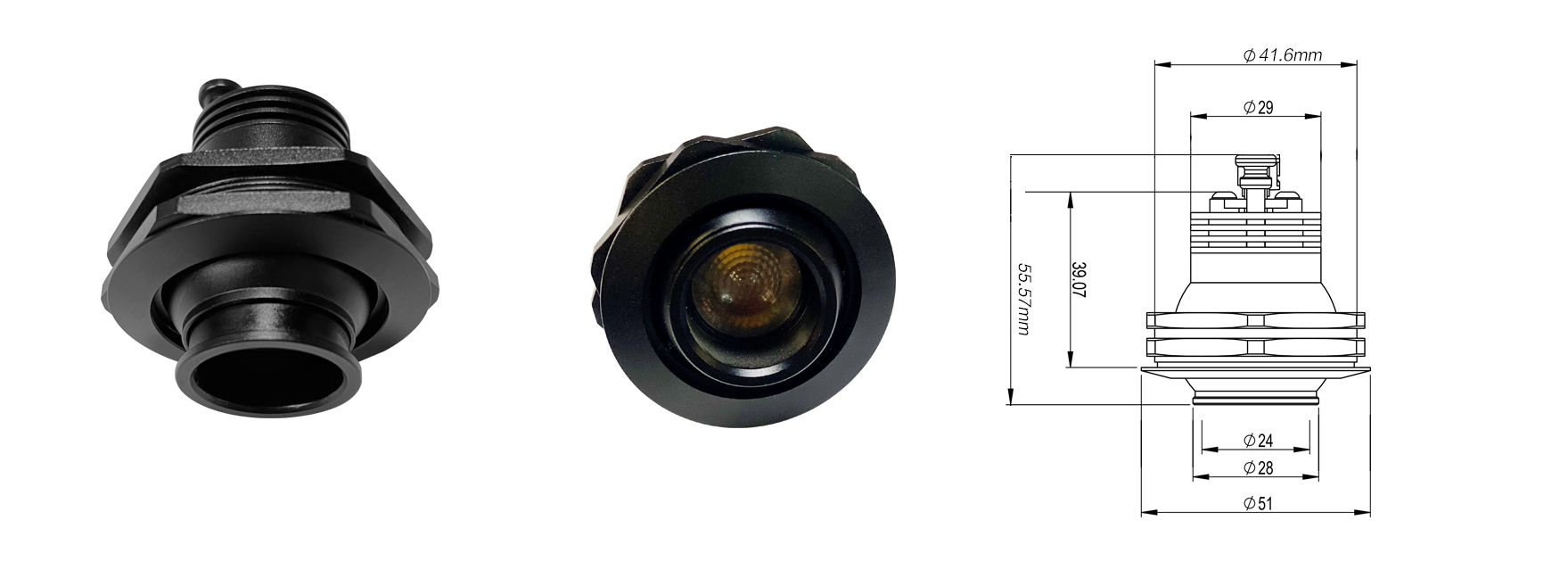
A considerate design more oriented from the spirit of sustainability and flexibility. A cabinet/showcase light can be controlled and maintained without opening the box!

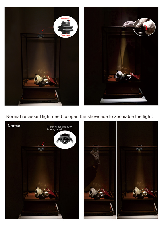
—Exteriors control and maintenance design
Control and maintain w/o opening the cabinet. That provides convenience for a more precise and perfect display. Equipped with set of pre-mounted brackets, the light can be changed and maintained easily. With an adjusting needle, the beam angle and the projecting direction can be adjusted freely.
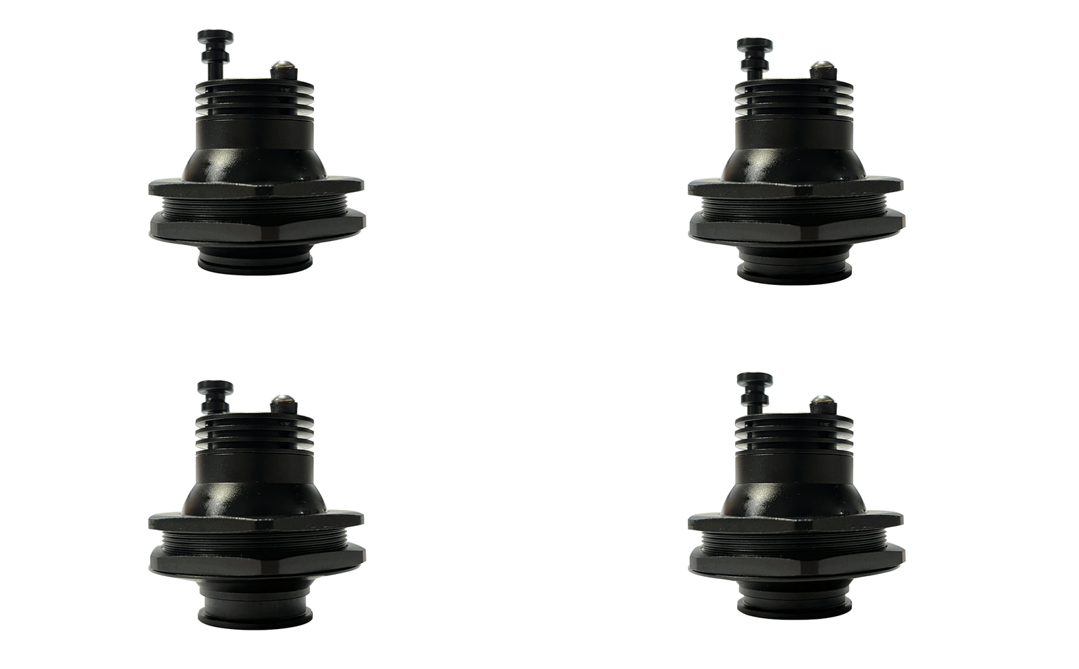
—Zoomable beam angle
A Built-in patented lens can be adjusted to achieve a stepless light zooming from 8º to 38º , agile for displaying individual object,
by operating conveniently from outside of the enclosed showcase.
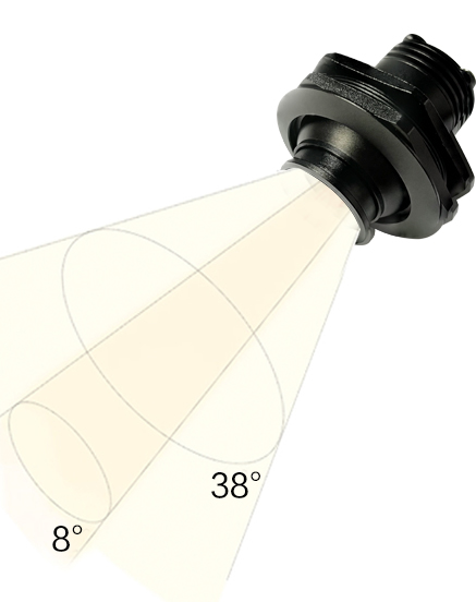
360°Horizontally directional

| Rolux #8088/3W & Y-tech AC100-240V | ||
| Light remodeling round to oval | Wattage : 3W | Quantity of LED: 1PC |
| zoomable technology | Beam Angle:3W/8°-38° | CRI: >90 |
| Light Stretching | Lumen: 3W 165 Lm | Input Voltage:AC100-240V |
| Different light texture | Colour Temp: 2700k/3000K/4000K | Housing: Black |
| Different light colours | Installation: Recessed | Weight: 3W/200g |
| Cutout: 45mm(42mm-51mm) | Certification:CE | |
| dimmable:DALI,… | Life time:30000H-50000H | Warranty:3 Years |
Application
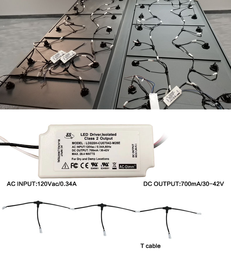
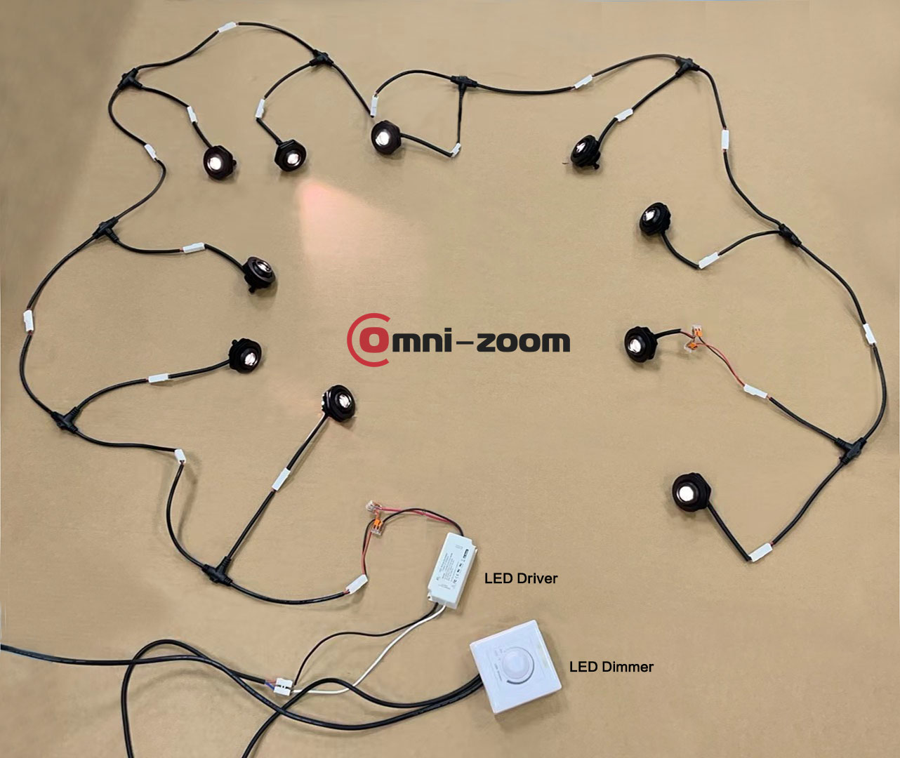
Power Driver Application 1: Eco Mode
A Power Driver connects 10 lights in series (Dim or No Dim must be together, individual light adjustment is not possible
1. AC INPUT.
Connect the AC INPUT terminal of the power supply to an AC power source, making sure the voltage is 120Vac.
Pay attention to the polarity of the power plug to ensure that it is properly connected to the Fire (Live) and Zero (Neutral) wires.
2.DC OUTPUT.
Due to the series connection, one end of each light is connected to the other end of the previous light, creating a continuous line.
Connect the DC OUTPUT positive terminal of the power supply (usually the red wire) to the positive terminal of the first lamp.
Connect the DC OUTPUT negative terminal of the power supply (usually the black wire) to the negative terminal of the last lamp.
3. Precautions
Polarity Matching: Make sure the positive and negative terminals of each lamp are correctly connected and not reversed.
Voltage distribution: Since the lamps are connected in series, the voltage on each lamp will be part of the total output voltage. It is necessary to ensure that each lamp can withstand the voltage allocated to it.
CURRENT LIMIT: The DC OUTPUT current limit of the power supply is 700mA, which means that the current of the entire series circuit should not exceed this value.
Wiring protection: During the wiring process, ensure that suitable insulation and terminals are used to prevent short circuits and the risk of electric shock.
Power supply capacity: Although the power supply is capable of supplying sufficient current (700mA), it is still necessary to ensure that the total power of the power supply can meet the needs of all the lamps.
4. Testing and verification
After the wiring is completed, do not turn on the power first to check if all connections are firm and correct.
Turn on the power supply slowly and observe whether the lights come on normally and whether there are any abnormalities (e.g. overheating, flickering, etc.).
If a problem is found, immediately disconnect the power supply and check if the wiring is correct or if there are any other potential problems.
How DALI works?
Power Drive Application 2: DALI power drive, capable of individual lamp dimming, can set different scenes for different lamps, and can be integrated into a smart home system through professional adjustment.
The following are the working steps and precautions for the four devices mentioned:
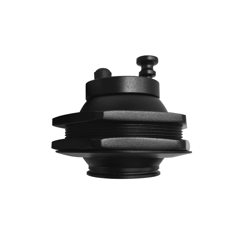
1、 the lamp you want (check the specifications and parameters of the lamps, especially the voltage and current requirements, so as to subsequently match the DALI power supply)
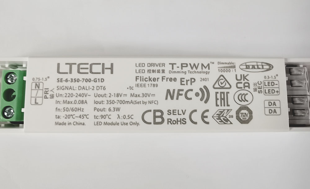
2、Matching DALI power supply (Make sure it is the voltage and current output of the DALI logo power supply that matches the voltage and current requirements of the fixture)
① Power supply output voltage Uout:2-18V (automatic selection)
②Power supply output current Iout:350-700mA(dial code)
③Dali logo
3、DALI bus power supply 9~16 volts (DALI bus power supply is responsible for providing stable voltage for DALI bus to ensure stable transmission of communication and control signals)
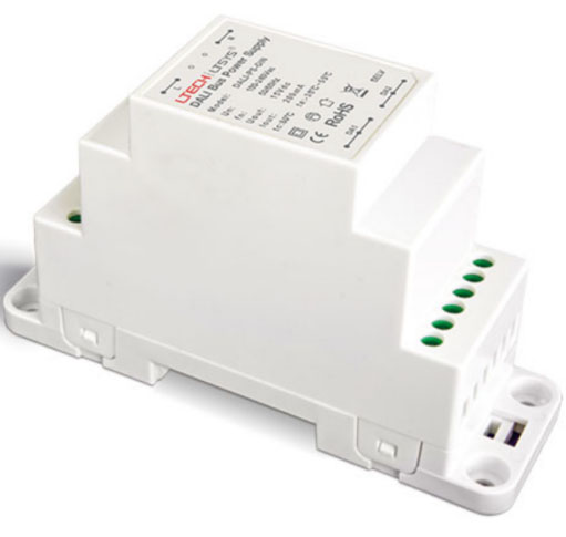
4、 DALI control panel (DALI control panel and DALI bus to connect)

5、Use the NFC Lighting APP
Scan the QR code below with your mobile phone and follow the prompts to complete the APP installation (According to performance requirements, you need to use a NFC-capable Android phone, or an iphone 8 and later that are compatible with iOS 13 or higher).

DAli used by amateur hobbyists (small projects)
DALI Wiring diagram
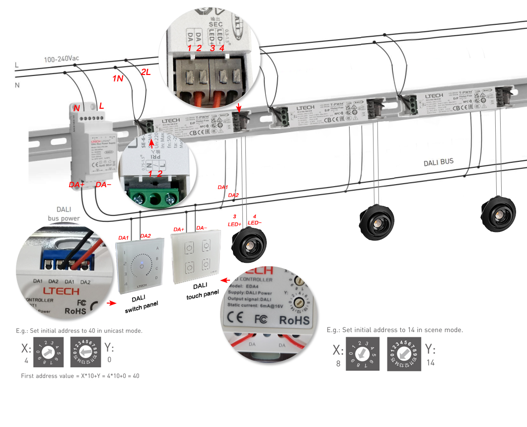

The debugging panel is only needed when debugging lighting, and ultimately we only need to use the panel to control the lighting.
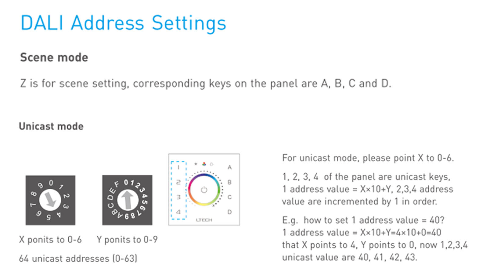
When mapping the ABCD scenarios of the DALI moderation panel to the 1234 buttons of the DALI usage panel, we need to clarify the functional match between each scenario and the buttons.
The ABCD scenarios of the DALI control panel represent four different preset lighting modes, each optimised for a specific environment or need. These scenario modes can be selected and switched by DALI using the 1234 button on the panel.
Users can easily switch to the desired profile by simply pressing the corresponding button for quick and easy lighting. This correspondence is designed to enhance the user experience and make smart home control simpler and more intuitive.
IES:
Datasheet:
Installation Indtruction:
Certification:
More:

